Capabilities
Programming:
Punch up to
Shear:
Grain:
Bend up to
Weld:
AutoCAD, Solidworks & Fabwin
0.250″ Aluminum & Steel
0.187″ thick Stainless Steel
0.010 to 0.250 thick materials
36″ wide x 144″ long, 5″ depth
0.250′ thick and up to 8′ long
MIG, TIG, Arch & Spot welding
Materials
- Aluminum
- Brass
- Copper
- Cold Rolled Steel
- Hot Rolled Steel
- Galvanized
- Stainless Steel
LINKS TO COMMONLY USED SHEET METAL PRODUCTS
Pem Engineering& Manufacturing: Manufacturers of PEM® brand threaded inserts, standoffs, studs and more. www.pemnet.com
Southco: Manufacturers of access hardware, latches, hinges and rivets. This site contains electronic CAD files that can be downloaded for use in designing your assemblies. www.southco.com
Wilson Tool International: Manufacturers of standard and special application tooling for turret presses. www.wilsontool.com
Tolerances
Best Practices in Tolerance Specification
Although the machinery and tooling will repeat within .004″, it is a mistake to simply engineer all mating parts expecting +/-.005″ accuracy. Such over kill forces additional labor in sorting and inspection. The result of tolerances that are too tight is simply higher cost and lower productivity. Correctly toleranced parts still have excellent fit and function, with the added benefit of manufacturing efficiency.
Hole Sizes
Holes are produced by forcing a punch tool through the sheet metal in order to rip out a slug. When the punch retracts the slug remains stuck in the die tool and a hole is left in the sheet metal. The size and shape of the punch and die tooling determine the size and shape of the hole. A minimum hole or relief size is determined by the thickness of stock to be used, for best results the punched feature can be no less than the material being punched. The die tool is slightly larger than the punch to minimize tooling wear and to reduce the pressure required to punch the hole. Generally speaking 10% of the material thickness is used for most applications. For example, the material is .100 % aluminum and the punch diameter is 1.000″, the die diameter would be 1.010″. The size of the hole on the punch side will be the same size as the punch tool. The size of the hole on the die side will be the same size as the die tool. Except for tooling wear, there is very little variation from one hole to the next. Vista Industrial Products has an extensive library of tooling, but we do not stock all possible tool sizes. This is why we look to the designers, engineers and draftsmen to give us a tolerance range that allows us some flexibility in using tooling that we have in house. When that is not possible, a capital investment in new tooling is required. Generally speaking, +/-.003″ is a reasonable and functional tolerance.
Hole to Hole
Accuracy of the distance from one hole to another is dependent primarily upon the machinery used to process the sheet. However, all holes and features punched through the sheet can introduce stress into the sheet metal. If the part has a closely spaced perforated pattern or formed features such as dimples or counter sinks the result can cause the sheet to warp and distort — this can cause unwanted variation between holes or features. If this condition exists, a greater tolerance should be applied to certain areas surrounding this characteristic.
Hole to Edge
Part profiles are punched just like any other feature except when using a machine with shearing capabilities; these dimensions should be considered the same as hole-to-hole. When punching close to an edge (less than double the material thickness) the edge can be pushed out by the stress of punching the metal. This edge movement can introduce variables in the accuracy of the hole location in relation to the edge. There are techniques to minimize this problem but whenever possible, engineers should allow +/-.010″ hole-to-edge. Tolerances of +/-.005″ should be used only when absolutely necessary.
Hole to Bend
Several factors have been introduced leading up to this stage in the fabrication process. Features and parts have been punched on a CNC turret press; line sanded or tumbled to remove burrs, and now is being formed on a press brake. The deburring process may remove .003″ when cosmetic appearance is a priority. Precision press brakes will position and repeat within the +/- .002″ range. Skilled brake operators are able to load the parts for forming consistently from bend to bend. Nevertheless, consideration must be given to the natural variation in material thickness (5% of nominal thickness), the +/-.005″ from the turret press, the effects of cosmetic sanding, and the variation introduced by the press brake. A tolerance of +/-.015″ hole-to-bend is functionally reasonable for most applications. Resort to +/-.010″ only when absolutely necessary.
Bend to Bend
Considering the variables that effect “hole to bend” tolerances, now multiple material surfaces and thickness are introduced. Whenever possible, engineers should allow +/-.020″ bend-to-bend. Resort to +/.010″ only when absolutely necessary.
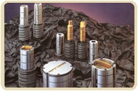
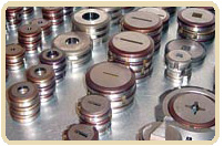
Tooling
Tedco has a large selection of standard punch tooling. Our special application tooling inventory can be used to countersinks, dimples, and counterbore. Tooling list available upon request.
When you need it tomorrow – it will be done today